Chapter 9 : Register File
In previous chapter, we made 1 bit flip flops, and connected them together, then we had registers. Registers are needed, but we can't say "We are great computer engineers because we have registers!". Registers have special organization in a computer, and that's called Register File. In this chapter, we will design a simple one!
The Decoder
Let's make another combinational circuit here. The circuit we are making here, is called Decoder .
Decoders have n selectors, and 2^n outputs. This is why they're decoders! You give them a binary number as
input and you take a hexadecimal number in the output. Of course, you never get the exact hex number at the output,
but you can find hexadecimal notation of input by using a decoder. Let's make one! The simplest decoder we make is a
2x4 decoder. According to 2^n, we can also make 1x2 decoder, but it's not actually a real decored. It's an AND gate!
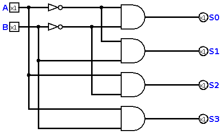
The logical function of a 2x4 decoder is like this :
S0 = ~A~B
S1 = ~AB
S2 = A~B
S3 = AB
So, we can implement our decoder like this :
But, how we use this in a Register File ?
Simple Register File
We have a 2x4 decoder. So, for now we can make a simple register file with four registers. The outputs of decoder, will be connected to Enabler pin of registers. Just like this :
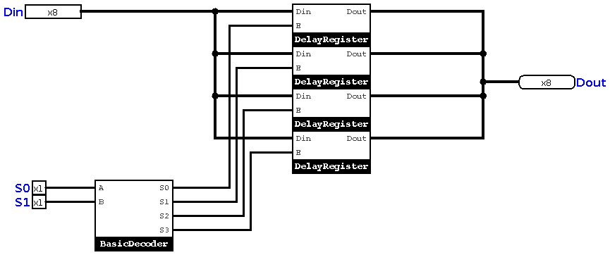
This is actually not a good design, it can generate a lot of noises, so we need another device, which allows us to select one of outputs!
The Multiplexer
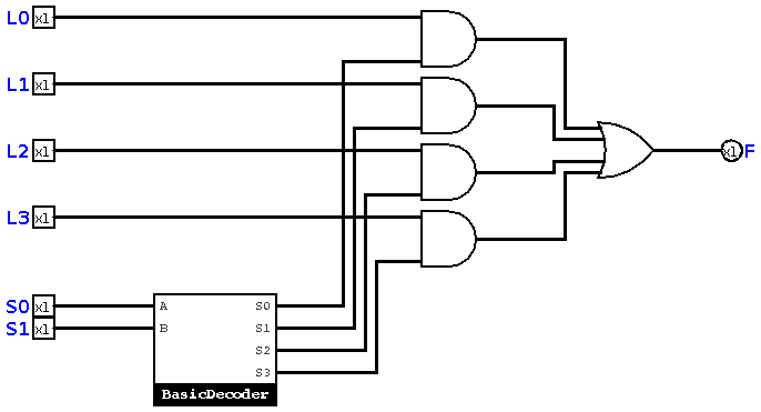
You know, we need a device which acts like a decoder, but it does a selection among input data lines. This device is called a Multiplexer. In this book, We call it Mux. A mux can be implemented using a decoder, and a bunch of AND/OR gates. Like this : This is a simple mux :
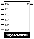
For our register file, we need a mux which can handle 8 bits input and output. So, I connect 8 muxes together, and I'll have a big mux like this :
Now, we can go back and complete our register file.
Advanced Register File
Now, we add a mux to the register file we designed, so we get this :
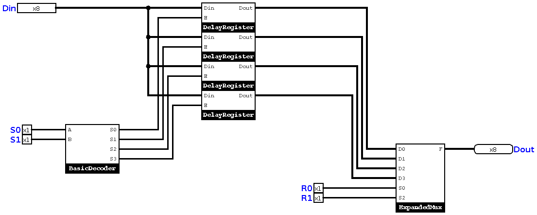
S0 and S1 are selectors for moving data to registers. we call that situation Store. And R0 & R1 help us read data from registers. This is what we call Load. We can claim that we have a Load/Store Architecture.
Ready for Architecture!
Computer architecture is not only engineering. It includes mathematics, philosophy, analysis, etc. We need to combine all of them, to design an architecture. In next chapter, we will take a look on the philosophy behind computer architecture. Then, we will start design and implementation of our microprocessor.